
Restoring a Ten Tec Omni Series C Transceiver – Part 1
The Ten Tec Omni Series C — An Awesome 80’s radio
I purchased a Ten Tec Omni Series C transceiver about a year ago for my collection. At the time, I was in the middle of several other projects, and didn’t get to it until just recently. I had been using an Omni D, but it still needs work and I thought the “C” would be a nice upgrade.

Released in 1980. the “C” was Ten Tec’s latest in their Omni series of radios. It improved on earlier Omnis, the series “A” and “B” (both with analog frequency displays) and the digital frequency display equipped Omni D. The “C” was the first Ten Tec radio to support all of the WARC bands. It also included all the 10 meter band segments without any optional crystals.
The Omni series “B” and “D” radios offered audio and optional crystal bandpass filters — a major upgrade from the optional audio-only CW filter of their earlier radios. It also added a notch filter for eliminating adjacent AM and CW carrier interference and a noise blanker. Like the Triton series, it produced 100 watts on all bands with a solid state final and featured a very sensitive receiver.
First Assessment
The radio was relatively clean, and didn’t appear to have any modifications. Hooking it up to the matching power supply, I began to verify receive and transmit on all bands, but there was an immediate problem. While CW and SSB signals were heard, they couldn’t be tuned in correctly. CW signals could only be heard at a very high pitch, and SSB signals couldn’t be brought onto frequency before disappearing from the passband. Even more strangely, pressing the “spot” button on the front brought those signals nearly on frequency.

Sensitivity varied from band to band as well. 160 meters was pretty deaf, and two of the 10 meter segments, 28.5 and 29 MHz produced a “9.000” instead of the correct frequency in the display. Not only that, but moving the band switch to 30 meters would trip the over current protection on the power supply.
The radio had transmitter output on some, but not all bands. For example, 160 and 18 meters had very low output. Other bands produced power, but would trip the over-current protection in the power supply before activating the “ALC” light. Also, the SWR meter didn’t seem to work on transmit. Clearly this radio was going to be a troubleshooting challenge.
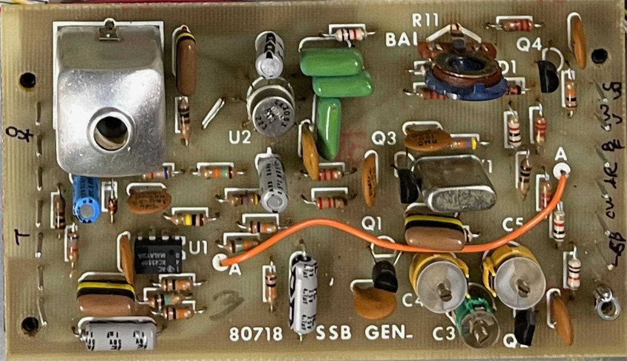
SSB Generator Alignment

After spending a little quality time with the Omni C manual, I decided that the SSB Generator must be out of alignment. While counterintuitive that signals in the transmit chain would effect the receiver, it turns out that the carrier generated by the SSB Generator is also used as a Beat Frequency Oscillator (BFO) and fed to the product detector on the IF-AGC board. If the carrier is off frequency, the receiver will not decode CW or SSB properly. To test my theory, I decided to try a “Carrier Oscillator Alignment,” described on the SSB Generator description in the manual.

In theory, it’s pretty simple. Three trimmer caps, C3, C4 and C5, set the SB/N, CW, and SB/R BFO frequencies. A frequency counter and VTVM or oscilloscope are all the test equipment needed. The beauty of the method is that it uses the transmitter to align the three carrier frequencies within the crystal filter passband. In the Ten Tec Model 546C manual, the alignment instructions are on page 3-40.
Adjusting the SSB and CW carrier frequencies
In practice, it’s a little tricky. It took me some time to understand what each trimmer did. Since C3 sets the basis for the other two adjustments, there is interaction between all three. Not only that, but minute adjustments of each trimmer have big effects. I ended up going through the procedure several times before I got anywhere close. Finally, I managed to get the within a few Hz of the specified frequencies.
The alignment of the SSB Generator corrected the CW and SSB decoding problem in the receiver. There is another adjustment on the board, T1, that is not mentioned in the alignment instructions. On a hunch, I tried adjusting it slightly and found it would peak the output of the Generator. First problem solved!
It’s hard to imagine that the three trimmer caps drifted off value in this bizarre fashion, and I suspect a previous technician had used a “diddle stick” on this board trying to solve some problem. As we will see in this restoration, there was ample evidence to support this theory.
The “Deadly” 30 Meter Band
Next problem, moving the band switch to the 10 MHz position from either direction would trip the current protection circuit and shut the power supply down. The protection circuit is meant to preserve the transmitter’s finals in the event of a high SWR condition, but it was hard to imagine how the band switch could be involved.

The band switch operates many rotary switch wafers on four boards in the radio through a system of shafts and a chain drive. Switch wafers are found on the RX-Trimmer, Oscillator-Mixer, Bandpass Filter and Low Pass Filter boards. I had already cleaned all the wafers with De-Oxit, but still suspected that one of those switches might have failed. Good luck finding a replacement!
A Surprising connection to the Digital Readout
Looking through the schematics for each board though, I noticed that one wafer on the Oscillator-Mixer board (S1-J) sent 13.8 volts through two wires to the Digital Readout assembly. As described in the Digital Readout description, this was designed to read the radio’s frequency with correct math.
The two lines from the Oscillator-Mixer select presets to display the actual frequency derived from the local oscillator and Permeability Tuned Oscillator (PTO aka VFO) frequency — 9 MHz away. Interestingly, the 10 MHz switch position had a wire all its own — isolated from the other positions. This seemed like a good place to start.

My first thought was there might be a fault in the Digital Readout assembly, so I removed it’s cover in the hopes of seeing something obvious like a smoked component. With the cover removed, I could see the control wires in question, and decided to trace them back to the Oscillator-Mixer board. In order to do that,

I had to remove the RX Mixer board, and there it was: a white/orange wire that connected the Digital Readout assembly with the Oscillator-Mixer board had been trapped between the RX-Mixer board and one of its sockets, pinching the wire and flattening the insulation. Looking at the foil side of the RX-Mixer board, I could see that the pinched area of the wire would touch a grounded area on the board. Could it be that simple?
The Smoking Gun (aka a pinched wire)
I detached one end of the wire, slid a little heat shrink tubing over the damaged area of the wire and heated it up. After rerouting the wire to avoid the connector,

I remounted the RX-Mixer board and checked for a short to ground with an ohmmeter. All was ok, so I powered the radio. The radio could now be switched to 10 MHz without killing the power supply. Second problem solved! Could our diddle-stick wielding technician have pulled the board out in search of a different problem and trapped that wire?
That’s enough for now. In the next post, I will tackle the SWR and ALC monitoring problems as well as alignments to improve receiver sensitivity and transmitter output — stay tuned . . .
I applaud your technical ability and your desire to keep these legendary rigs in great shape. Bill wb4edb