
How to Upgrade the Ten Tec Omni C with the K3JLS DDS VFO
Upgrading the Ten Tec Omni C PTO to a DDS
I was having a lot of fun with the restored Ten Tec Omni (series C), but like all of the older Ten Tec radios, the Permeability Tuned Oscillator (PTO), aka VFO, left a little to be desired. Back in the day, when I bought my first Ten Tec, these PTOs were considered very good — but time marches on and we’ve gotten used to smoother and more stable VFOs. An upgrade would be nice.
A Digital VFO

Then, while cruising eBay one day, I noticed a “Dual Digital DDS VFO DIY Kit for Ten-Tec and Drake TR-5/7 Radios.” Upon reading the ad, I learned that it would work with several Ten Tec radios, including the Omni Series C. The eBay seller would provide a printed circuit board, two pre-programmed PIC microcontrollers (in case one is damaged by static electricity), a schematic and assembly instructions. The buyer is responsible for obtaining all the other parts and assembly. Listed at $47, it didn’t sound unreasonable considering all the work of designing the circuit and PCB, so I ordered one. I had it in a few days.

The kit relies on an “AD9850-based 40MHz DDS Function Generator Module,” available on eBay and Amazon. This module does much of the heavy lifting for the VFO, and costs about $22. A parts list and schematic is obtained from K3JLS’s Web site, and it includes part numbers for Mouser. I ordered them and had everything in a week or two. I did buy one extravagance for the project though — an original “Ten Tec Omni VFO Knob” for $45. All together, I spent about $200 including a slanted-front metal case. — a little expensive, but more professional looking.
Other Features
Besides being a stable VFO with repeatable 10 Hz resolution, this kit offered dual and split operation — features that would have required an outboard VFO back in the day. You can find the matching VFO for the Omni-series radios, but they routinely go for over $150. For the cost of the original outboard VFO, the kit offered much more.

When the kit arrives by USPS, a label on the front advises “For construction/testing/installation information see: http://www.k3jls.net/box.html. You find a very long and detailed Web page with a lot of information about the kit. I printed the page out, but there are also internal links needed for the project. I ended up printing about 25 pages before I had all the information I needed.
Who is this kit for?
I would recommend this kit for experienced builders. It is through-hole construction with no surface-mount components, but the parts are small and can be difficult to identify. There are a couple of small errors in the build instructions, and the DDS board and ATMega processor are static sensitive. Appropriate precautions should be taken. A fair amount of metal work is needed to enclose the project. Finally, modifications may be needed to use the VFO with a Ten Tec radio, depending on what options are desired.
The Build
There is a lot of information at http://www.k3jls.net/box.html. I recommend reading all the instructions before beginning the build. They are specific for using the DDS VFO with either Drake TR5/TR7 or Ten Tec Triton/Omni radios, but the kit could be used with any transceiver that has a 5-5.5 MHz VFO. It can be installed internally or in an external case. Examples of several finished versions are provided via links on the Web page.
A little confusion and a few problems
One bit of confusion for me was the reference to both Version 3 and Version 4 boards. It wasn’t clear to me which version I had initially — the board silkscreen doesn’t say. By process of elimination, I was eventually able to determine that I had Version 4. This is important because there are small differences in the build between them.
The designer provides a clear explanation of how it works
The kit designer thoughtfully provides an introduction and description of the circuit at the “30,000 foot view.” From that section, one gets an idea of how the device works. Next, some general advice for kit building is provided. Don’t skip this section, as there are important tips like “ensure that you are mounting the components on the proper side of the blank printed circuit board” along with the proper board orientation.
Comprehensive build instructions
Build instructions for the board are divided into 24 steps. They are very detailed, but have a few errors so a little interpretation is necessary. As I was working through them, I wondered if the discrepancies were due to differences between the Version 3 and 4 boards. I was able to resolve all of the questions by referring to the schematic after reading the instructions carefully. Just take your time.

There is a substantial test process of 12 steps for the assembled board. None of it is difficult — just follow the directions. Thankfully, mine passed without trouble. I had interpreted the assembly instructions correctly.
The Enclosure

After assembling and testing the board, it was on to the enclosure. There is one other somewhat exotic part here, the Encoder. The designer mentions three acceptable parts, each resulting in a slightly different tuning rate. I ended up getting the Bourns part with a pulse rate of 128 quadratures per revolution (the slowest tuning rate) and I really like it. It is also the most expensive version of the three recommended parts at about $21 on eBay.
Enclosure details are included with separate sections for Drake and Ten Tec in a followup section of the instructions. I had decided on the recommended slope-fronted box for my build, and several examples are shown on the Web site.
Metal Work

Laying out and drilling holes to mount the various components took a fair amount of time. I used blue painter’s tape and a fine-tipped Sharpie to avoid marring the painted cabinet. A spring-loaded center punch and drill press are helpful for accuracy, but one could make all the holes with an electric hand drill.

Nine holes are needed on the top and front of the cabinet to mount the LEDs, Main Tuning Knob, Offset Control and four switches. I spent extra time with this layout because I wanted to end up with a pleasing and ergonomic arrangement.
The back panel requires two holes for the Power and VFO Output, and a third hole for Transmit Input from the transceiver. More on this later. Several holes are also required to mount the circuit board and voltage regulator. The case acts as a heatsink for the regulator.
Final Assembly

Fitting the 1/4-inch tuning knob
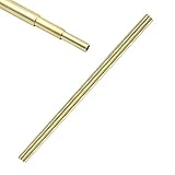
The encoder came with an 1/8″ shaft that won’t fit standard knobs. I later learned that the same encoder can be purchased with a 1/4″ shaft, but I already had the 1/8-inch version. After a little head scratching, I realized that some brass tubing from another project could make the transition. It was three pieces of concentric tubing that fit together. By using short pieces of the two larger tubes, I could transition from 1/8 to 1/4-inch. I just soldered the two tubes together, and then epoxied them to the encoder shaft. Voilà!
The Expensive Knob

You may be wondering why I spent $45 for the tuning knob. Many others would have served the purpose. This isn’t just any knob though. Besides being weighted and matching the tuning knob for the Ten Tec Omni V and VI series radios, it has a hidden feature — an adjustable brake to set the drag. On the underside, there are two little felt squares mounted on some springy copper strips.
By pressing the dial skirt toward the panel and twisting, these felt pieces can be adjusted to provide varying amounts of drag as you spin the knob. I have mine set with only a slight amount of drag, and a quick spin of the weighted knob results in a satisfying gradual slowing of the knob to a stop. It feels deluxe and expensive.
Radio Connections
Three connections are required for VFO operation; Power, VFO Output, and Transmit Input. Power can be taken from any 12 to 13-volt source, and is available on the back of the Omni. VFO Output is connected to the VFO input of the Omni after removing the factory jumper.
Transmit Input is connected to the “R” lead on the Control Board. This line goes to ground when the radio is in transmit mode. You can bring the line out by borrowing one of the unused phono connectors on the back of the radio after removing and insulating the attached wire. The VFO will function without this modification to the radio, but without it, the “dual and “split” modes of the VFO will not work.
Adjustment
There is only one adjustment for the VFO — setting the output level. It’s important for it to match the level from the original VFO, and it is set using the 10-turn trim pot on the board. The process is described in the instructions and can be done with an oscilloscope or high-impedance voltmeter. Too high an output level can result in “birdie” generation and an increase in the receiver’s background noise level.
On The Air
The DDS VFO adds some welcome, modern features to the Omni C. I really enjoy the ease and stability it adds. I’m not much of a contest or DX operator (yet), so I haven’t needed the split mode much. I do like having a second VFO because I can move from the Phone to CW portions of the band quickly, or “remember” a frequency I want to come back to later. Locking the frequency comes in handy at times as well.
CW operation is a little quirky. As K3JLS explains, because offsets can vary from radio to radio, it would be hard to predict and program something that would please everyone. Therefore he suggests using the RIT control to set a CW offset if desired. That seems to work, but it depends on having the Transmit Input wire connected to the “R” line in the Omni. Otherwise, the transmitter will be on the offset receive frequency — confusing for phone operation!
All-in-all, I’m happy with this addition to my classic Ten Tec Omni C. It’s just the update the radio needed.

One Reply to “How to Upgrade the Ten Tec Omni C with the K3JLS DDS VFO”