
How to Restore a Dynaco ST 150 Audio Amplifier
Restoring a Dynaco ST 150 Stereo Amplifier

Lately, I’ve been restoring a Dynaco ST 150 stereo amplifier. As my collection of classic vinyl grows, I’ve assembled a decent 1970’s playback system. Coming of age in the mid-70’s, I coveted a new high-power solid state amplifier. I read Popular Electronics issues (e.g. Oct., 1970) with interest, especially the articles that described amplifiers like the Southwest Technical Products “Universal Tiger” — a 125-watt per channel beast.
They were beyond my reach, so I settled for a home-brew tube amplifier that used 6L6’s for the output stages. Tube equipment was common and relatively cheap then, while the high power solid state amps were new and exotic. Kind of an ironic twist on current audiophiles’ fascination with tube equipment, eh?
Re-living the 70’s in Stereo

There was another player in solid state kit amplifiers though. You may have read my previous posts on the Dynaco Stereo 80 and Stereo 120 models, so my interest in their bigger brother, the ST 150, shouldn’t be surprising. One came my way recently, in working condition with reasonable cosmetics.
I planned to use it with the Audiophile Phono Preamp described in an earlier post, a pair of Polk RTi-38 speakers and a Realistic Lab-400 direct drive turntable equipped with an Ortofon Super OM10 cartridge. The ST 150 would complete this simple, pristine (I hoped) vinyl playback system. All was well, until a final test on the bench after cleanup. I turned the amp on and the left channel emitted an ear-splitting howl that ended my dreams of a quick win.
A few technical details from 70’s amps

The ST 150 outputs are DC coupled, meaning there are no large output capacitors between the speakers and the final amplifier transistors. This is good for low frequency response, but if one of the output transistors fails, it can also mean the death of a speaker. I suspected the worst. The output transistors are easy to remove and test, and although none of them had failed, they were not well matched. In fact, each channel had different transistors altogether — with mismatched gain figures. I was going to need new output transistors at least.
I guess I’ll have to restore it after all . . .

The ST 150 was originally available either as a kit or factory assembled, and it wasn’t hard to find an assembly manual online. The amp I had was well made — either a factory job or a skilled kit builder. Examining it closely, it was also clear that there had been a previous repair.
Maybe I should replace the capacitors as well. The original output transistors were no longer available from Mouser or Digikey, but I found several sellers with “new old stock” on eBay. There were also Chinese versions available, but those would take at least a month to get. It was starting to look like a complicated task to buy parts.
Then, a stroke of luck. While looking through YouTube videos showing the restoration of an ST 150, I learned of an eBay seller (Fantasia Audio) that offered “matched sets” of output transistors. The same vendor also offered complete capacitor and semiconductor kits. Before long I had the outputs and a capacitor kit on the way. I opted not to buy the semiconductor replacements since they were less-likely to have deteriorated than the caps.
What about upgrading the power supply?

The amp has a beefy power transformer feeding a bridge rectifier and two 10,000 µF, 100-volt capacitors. UpgradeMyDynaco.com recommends replacing these caps with newer models that pack 22,000 µF into the same diameter package. I found some Hitachi capacitors that nearly matched original’s size, just a tiny bit shorter. They were the most expensive part of the upgrade, weighing in at $60 for the pair. According to Upgrade My Dynaco, this would greatly improve the regulation of the plus and minus 50-volt supplies. All the parts arrived in a couple of days.
The surgery begins . . .

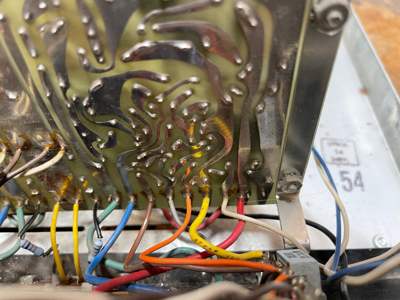
I had to remove the main circuit board in order to replace most of the capacitors. It isn’t very hard, but does involve desoldering 28 wires. They are color coded, and pretty easy to see where they go when replaced. I took a couple of photos for reference to confirm their correct orientation.

The double-sided board is high-quality fiberglass with plated-through holes, so a pro-level soldering iron like the 40-watt Weller WLC100 works well. You need enough heat to quickly remove each wire without damaging the circuit board. While removing the wires, I discovered the cause of the howling speaker: the wire providing minus voltage to the left channel had broken off. You can see it in the photograph.
When DC coupled amps fail, speakers suffer

How do I know that a problem in the output stage can destroy a speaker? Hooking my test speakers up to a different amp so I had music while working, I discovered that the left channel woofer was blown. Frozen cone. There must have been enough DC flowing to heat and destroy the voice coil.
Fortunately, I was able to find a replacement woofer for the Polk T15 on Amazon for about $20. As you can see, the speakers are an almost exact match. The Amazon version is very slightly bigger and doesn’t quite fit the cut-out in the speaker baffle. I was able to make it work although the frame of the speaker sits just a little proud of the enclosure. With the grill cloth in place, you can’t tell the difference.
Replacing parts on the circuit board

The same tools are also helpful when removing the old parts. Pay attention to the polarity of the electrolytic capacitors — matching the original capacitor orientation is critical.

There was one surprise with the supplied replacement parts. The original polarized tantalum capacitors are replaced by non-polarized electrolytic versions. Working carefully, it took me two sessions of about 2 hours each to replace all the capacitors on the circuit board.
Check your work — again.
I spent a fair amount of time looking the board over for errors. Shorts, correct capacitor polarity, good solder connections and so forth. I also checked connections with an ohmmeter where components connect the two side of the board. Mostly those are the ground side of bypass capacitors, but low-impedance connections are important for minimal noise and amp stability. When I was sure of my work, I cleaned the solder flux off the board using a little alcohol and an old toothbrush.
Reinstallation of the circuit board involved replacing all 28 wires I had removed earlier. The reference photographs made for peace of mind as I worked since I could see where each color-coded wire had been removed.

With the circuit board reinstalled, it was time for the output transistors. I had specified a matched pair, and used a transistor tester to measure the gain and Vf of each transistor. They did indeed match very closely.
They attach to the amplifier with two screws each, and a thin coat of silicon grease aids with heat transfer to the heat sink. They only can be oriented one way because the leads are slightly offset, but one must be sure to get the NPN and PNP transistors into the correct socket. Reversing them will result in the untimely demise of new transistors.
Adding a Current Inrush Limiter
The power supply upgrade creates a new problem. More than doubling the size of the filter capacitors from 10,000 µF to 22,000 µF creates a substantial current surge when the amp is powered. It is large enough to blow fuses and perhaps even the rectifier bridge.

Fortunately, there is an easy solution: the addition of a “negative temperature coefficient” (NTC) current inrush limiting thermistor. Fantasia Audio also has this part and even recommends the correct size in their eBay listing. It is simply connected in series with one leg of the AC line. Conveniently, there is an unused terminal strip originally intended for the conversion of the amp to 240 VAC. I don’t plan to use this amp in Europe, so it now supports the thermistor.
Replace the two-wire power cord!

Sound equipment from the 70’s is almost always equipped with a two-wire power cord. Because the ST 150 has a transformer-isolated power supply, it’s not really a safety issue, but it may lead to hum problems. When connected to audio equipment that has a three-wire power cord, there may be hum. I discovered this when I connected the ST 150 to the Audiofile Phono Preamp.
This was a head scratcher until I realized that the shield on the phono input connections was floating with respect to AC ground. This could induce a tiny hum signal at the amp’s input. Replacing the two-wire power cord with a three-wire version solved the problem by guaranteeing both chassis’s are at the same potential. It also adds a little extra safety in the remote chance that the power transformer should fail.
Last step: Bias Adjustment

With new capacitors, output transistors, inrush limiter and power cord installed, it was time for bias adjustment. It can be summarized as follows: interrupt the positive voltage to each channel by removing a fuse, and inserting an ammeter to measure the channel’s bias current. There are two adjustments: the overall channel’s bias current, and zeroing the channel’s output voltage. The ST 150 assembly manual describes the process, and I was able to complete the adjustment for both channels. There weren’t any wiring errors — relief!
Sound Check

Since completion, I’ve done a little listening, and it’s clear that this simple system — Phono cartridge -> Phono Preamp -> Power Amp -> speakers — is different. There are no adjustments except for a volume control. There are no tone controls and no “loudness” filter. The sound is bright, crisp and very dynamic. It has plenty of power and takes full advantage of the Polk RTi-38s, which I’ve grown to love over the years.
It will be interesting to try different phono cartridges for comparison. I’ll have to live with it a while to see if I like it, but I suspect I’ll be looking for a quality preamp to front-end the power amp. Subtle adjustments might be nice. Nevertheless, I’m looking forward to exploring this back-to-basics audio experience.