
Epic Restoration of a Ten Tec Triton IV – Part 2
Debugging the Ten Tec Triton IV
In the last post, I described a used Ten Tec Triton IV (aka Model 544) and addressed the most immediate issues. I also mentioned making a cosmetic restoration, but after using it in the shack for an evening, it was apparent there were other problems. The “Offset Tuning” (OT) LED didn’t work, and more seriously, the transceiver didn’t always mute in transmit. Strange sounds issued from the speaker at times. Cosmetics would have to wait.
The Awesome Ten Tec Manuals
 One great thing about Ten Tec products are the manuals that come with them. The Triton IV is simple to operate and requires only a few pages of operating instructions. The manual is much larger though, including complete circuit descriptions and alignment procedures for each circuit board in the modular radio.
In addition to that, voltage measurements are provided for each pin of each board, in both transmit and receive modes. That helps locate problems quickly. Ten Tec really wanted to enable their owners to service their own radios.
Replacing a “DED” (Dark Emitting Diode)
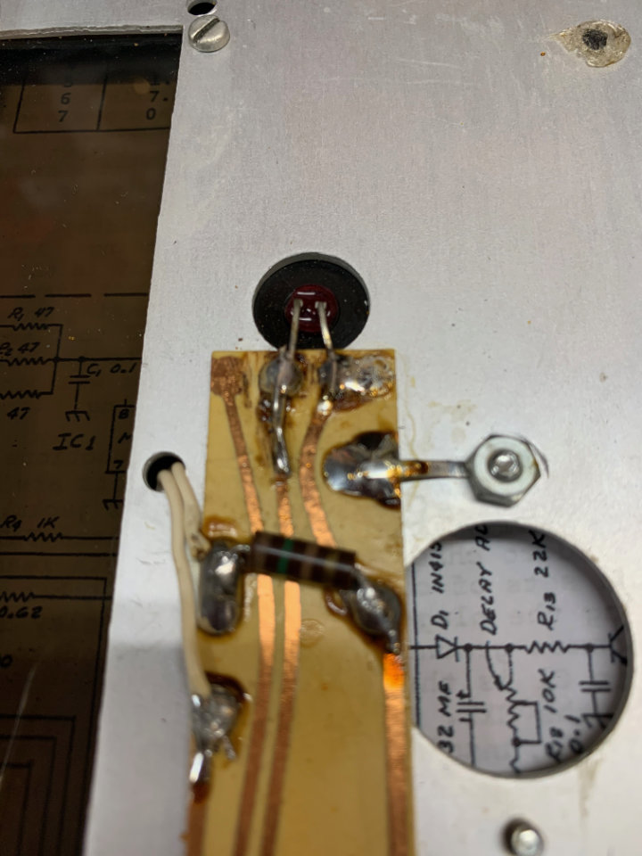
Starting with the offset tuning LED, I discovered that the voltage for it is developed on the 80281 OT-TR Board. It is located on the top right-hand side of radio near the back. It’s a simple circuit, with a transistor connecting the cathode of the front panel OT LED to ground through a 680 ohm resistor. The other side of the LED is connected to the +12-volt supply. The voltage measured on the “OT-Lite” pin was very low on both transmit and receive modes instead of the expected 13.8 to 12.0 volts (transmit and receive).
Either the wires connecting the LED to the board and 12-volts were open, or the LED was defective. I already had the front panel of the radio disassembled, so it was easy to test. LEDs don’t fail very often, but this one was open. A rummage through my junk box produced a matching replacement and it was quickly installed.

Finding the Intermittent Muting Problem
On to the muting problem. This was somewhat intermittent, but luck was with me and the problem persisted long enough for me to find it. Initially, I thought about feedback in the receiver path because the problem seemed to appear as the drive control was advanced when transmitting.
One puzzling thing, it wasn’t consistent across all bands, and seemed worse on the lower bands like 80 and 40 meters. Not only that, but it didn’t always happen. So I started with a “scatter gun” approach; I began measuring voltages on various boards and comparing them with the predicted values in the manual.

Reasoning that the 80287 TX-RX Board processed both receive and transmit signals, I started there. Perhaps some kind of feedback was happening between them. I pulled the board out and inspected it carefully under magnification and found what looked like a couple of poor solder joints. Over the years, Ten Tec was notorious for sketchy solder work, and I had read several accounts of correcting problems by resoldering connections.
I’ve got it! — Well, No.

I got excited thinking I had found the problem, but it was a phantom. There was no change in the radio’s behavior. In retrospect, it’s a good example of how what we expect to find can lead us away from the real problem.
After chasing that rabbit down the hole, I finally noticed the inconsistency in the T/R logic voltages. That led me to the 80280 Control Board where they are generated. Ten Tec also provides voltages on active devices, so I was able to check each of the transistors for operation.
A Short Description of the Triton IV’s Keying Logic
The Triton IV uses several voltages to go from receive to transmit. They are labeled “T/R” (transmit/receive – low on transmit), “T” (transmit – high on transmit), “R” (receive – high on receive), and “tD” (transmit delay – high after delay on transmit).
The sequence starts any time the “T/R” line is pulled to ground by either the push-to-talk (PTT) on the microphone or the key line is closed. The “T” line then goes high, which switches off the normally present “R” voltage. Finally, the “tD” voltage is generated after a small delay to facilitate sequential keying of CW without key clicks.
These three voltages, “T,” “R,” and “tD,” activate various parts of the transceiver for either receive or transmit operation. The small time delay in the transition from receive to transmit allows full break-in CW (QSK). It’s a big part of the full-QSK operation that Ten Tec perfected before most manufacturers back in the mid-1970’s. These signals are generated on the 80280 Control Board, on the top right of the radio near the front.
You’re Getting Hotter, Hotter . . .

The transistors all tested good, but there was an inconsistency on the base of Q2 where the “T/R” signal is first used. I tend to suspect electrolytic capacitors first, and there was a 1 uF cap in the base circuit, so I desoldered it for test. It had changed value. I ended up replacing it and the other electrolytic cap on the board (used in the regulated power supply for the VFO and Offset Tuning circuitry) just for grins. Back in the radio, the board now operated normally.
Did I actually find and fix the problem? Time will tell. As with all intermittent problems, we might never know for sure, but it seemed plausible that the defective cap where the “T/R” line is processed might result in flaky operation. As the drive was increased to the transmitter and the final amp drew more current and loaded the power supply, lower supply voltage might have caused the problem.
Now Can We Clean it Up?

I had now completed repairs to the radio. I tested the receiver sensitivity with an Elecraft signal generator, and measured output power into a dummy load with a scope. Everything seemed to be in spec, and operating normally. It was time to make the cosmetic restoration of the Triton IV.
2 Replies to “Epic Restoration of a Ten Tec Triton IV – Part 2”